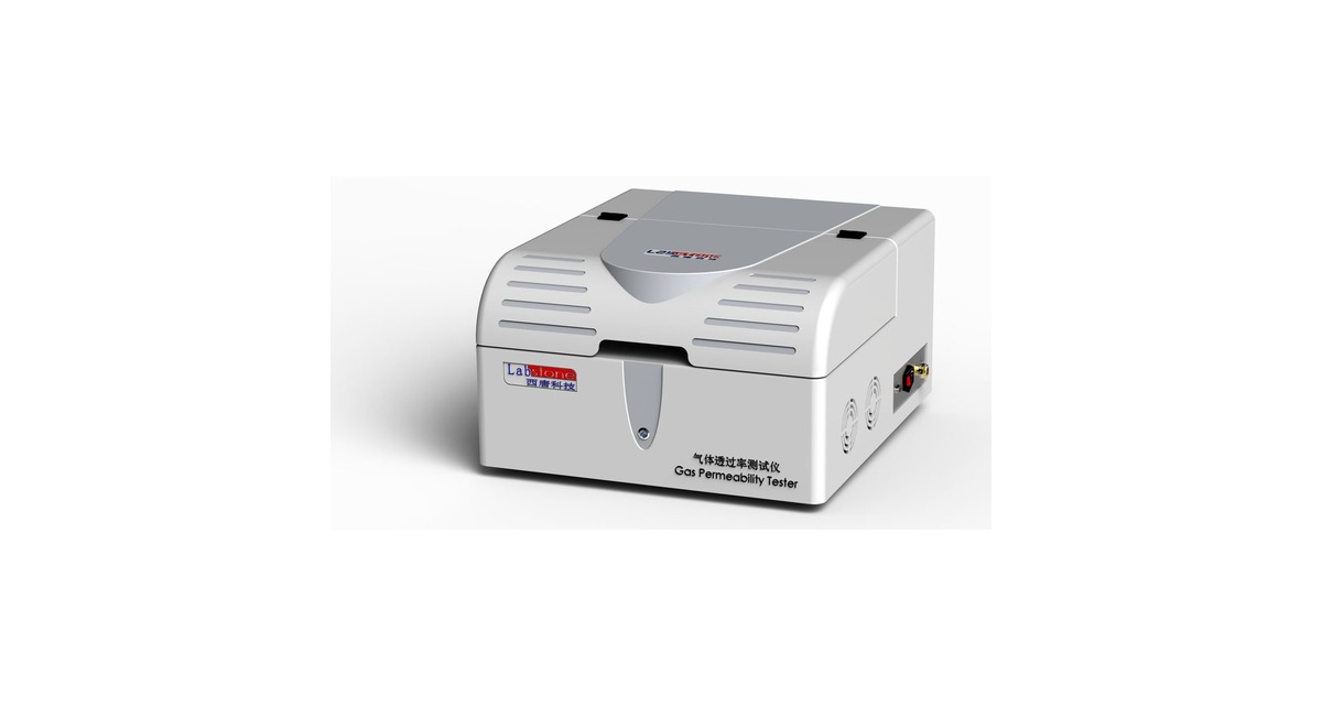
Differential-pressure testing is the classical way to quantify gas transmission through plastic films and sheets. The specimen clamps between two chambers: the high-pressure side is charged with the test gas, the low-pressure side is evacuated, and the resulting pressure difference — typically 0.1 MPa — drives gas through the film. A sensitive pressure sensor tracks the pressure rise on the low-pressure side, and the slope of the steady-state region gives the gas transmission rate in cm³ per square metre per 24 hours per 0.1 MPa. Internationally the method is specified by ISO 15105-1:2007, with ISO 2556 and ASTM D1434 Method A as widely cited equivalents; national editions keep the same geometry, conditions and calculation. Because one specimen mount serves any non-toxic gas, it remains the reference choice for permeability-coefficient work. The test temperature is typically 23 °C ± 2 °C, extended by agreement.
1. The 2022 revision: one method split into two parts
Older editions of the differential-pressure method packed principle, apparatus and procedure into a single text. The 2022 revision split it in two: a differential-pressure part and an equal-pressure part published the same day, mirroring ISO 15105-1 and ISO 15105-2, so both method families now sit under a consistent numbering scheme that customers and accreditation bodies can cite without ambiguity. The revision also formalised two low-pressure-side detection routes — a sensitive pressure sensor and a gas chromatograph — and anchored thickness measurement to a dedicated film-thickness standard. For laboratories the effect is a clearer decision tree: differential pressure for multi-gas and permeability-coefficient work, equal pressure for continuous oxygen monitoring. Newer general specifications for laminated films cite the method standard directly, so quoting the current edition matters whenever a report is audited, and thickness data now carry a traceable measurement anchor.
2. Principle and the two detection routes
The physics is simple; the execution is not. The specimen separates two chambers: the low-pressure side is pumped down, degassed to clear adsorbed gases that would masquerade as transmission, then isolated from the pump, while the high-pressure side receives the test gas at about 0.1 MPa above vacuum. Gas crosses the film under the pressure gradient and the sensor logs the pressure rise on the evacuated side against time; the steady linear section is the measurement. Monitoring the evacuated chamber before gas admission yields the system baseline leak, and that baseline — sealing faces, gaskets, pipework — sets the detection floor of the whole instrument. A vacuum-greased seal helps, but excess grease contaminates the sensor or blocks the film edge. In routine work the sensor route covers everything from mid-barrier laminates upward; the chromatographic route is reserved for cases where the transmitted gas must be identified as well as quantified.
3. Specimens and test conditions
Specimens should be flat and free of wrinkles, pinholes and stains, about 97 mm in diameter and no thicker than 3 mm, with at least three replicates per condition. Thickness is measured at five or more points on every specimen under the film-thickness standard and averaged. Hygroscopic materials need thorough drying, or conditioning of 48 hours or more in the standard atmosphere, because absorbed water changes both free volume and seal quality. Metallised films and thin foil are handled gently at the clamp — a crease formed there is a pinhole in disguise. Vacuum grease on the sealing faces stays thin and even: enough to seal, never enough to migrate onto the film or sensor. Conditioning and handling together decide more borderline results than the instrument does: two specimens from the same roll, mounted and conditioned differently, can differ by double-digit percentages, which is why the replicate requirement exists and why the conditioning history belongs in every report.
| Item | Requirement |
|---|---|
| Test temperature | 23 °C ± 2 °C (typical; extendable by agreement) |
| Constant pressure difference | 0.1 MPa (test gas on the high-pressure side, vacuum on the low-pressure side) |
| Specimen | Φ97 mm, thickness ≤3 mm, no wrinkles or pinholes |
| Replicates | ≥3 per condition |
| Thickness | ≥5 points per specimen, film-thickness standard |
| Test gas | O2, CO2, N2, air etc., purity ≥99.5% |
| Results | Three significant figures |
4. Calculation and units
The transmission rate is taken from the steady linear section: the pressure-rise rate on the low-pressure side is corrected for the chamber volume and the test area and converted to the equivalent volume at standard temperature and pressure, reported as cm³ per square metre per 24 hours per 0.1 MPa — also expressible in cm³ per square metre per day per pascal or in mol per square metre per second per pascal. Multiplying by specimen thickness converts the rate into the permeability coefficient, the material-intrinsic figure used to compare films of different gauges. When replicates scatter widely, the first suspects are sealing faults, an uncorrected baseline leak, or specimens that were not conditioned alike — not the material itself. Keep the unit basis documented in the report template: a rate quoted on the wrong pressure basis is one of the most common inter-laboratory discrepancies, and it stays invisible unless the basis is stated alongside the number.
5. Method choice and international counterparts
Differential pressure and equal pressure answer different questions. Differential pressure tests any non-toxic gas on one specimen mount and delivers permeability, solubility and diffusion coefficients; the equal-pressure, coulometric route is oxygen-specific and reaches far lower transmission rates. The international family maps cleanly: ISO 15105-1:2007 for the manometric differential-pressure method, ISO 2556 and ASTM D1434 Method A as widely cited equivalents, JIS K7126-A in Japan. Whatever the badge on the report, confirm the edition cited in the customer specification — quoting a withdrawn edition invites a retest. When two laboratories disagree on a high-barrier film, running the same geometry under the other method family is a legitimate cross-check. For a packaging laboratory the practical decision is short: decide which gases matter to your product claims, decide whether permeability coefficients or transmission rates are contractually specified, and match the instrument family accordingly — differential pressure for multi-gas and coefficient work, equal pressure for oxygen shelf-life screening, or both when specifications mix the two.
- Differential-pressure method: specimen separates test gas and vacuum, constant 0.1 MPa difference, rate from the steady pressure-rise slope
- Two detection routes: sensitive pressure sensor (routine) and gas chromatograph; the equal-pressure part was published the same day
- Conditions: 23 °C ± 2 °C, Φ97 mm specimens up to 3 mm thick, ≥3 replicates
- Thickness at ≥5 points per specimen; test gas purity ≥99.5%; results to three significant figures
- Units: cm³/(m²·24h·0.1 MPa); permeability coefficient = transmission rate × thickness
- Counterparts: ISO 15105-1:2007, ISO 2556, ASTM D1434 Method A, JIS K7126-A